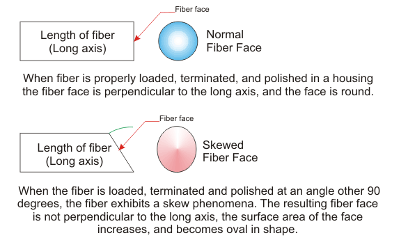
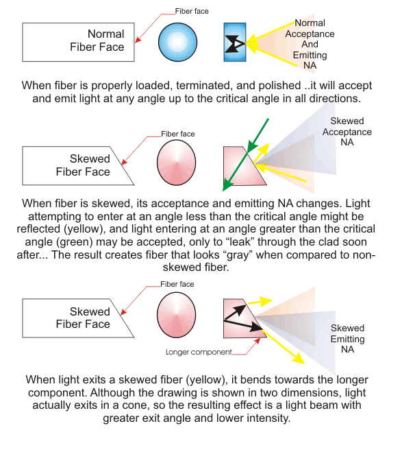
Testing has shown that fiber skew causes great differences in light transmission between otherwise identical parts. Defining fiber skew is simple. Understanding the impact, and how to control the occurrence, is more complex. Fiber skew occurs if the end face (of the fiber) is not cut at a 90 degree angle (perpendicular) to the long axis of the fiber. The result of this process is shown below.

Practically speaking, no part is entirely free of skewed fiber.
When done unintentionally, skewed fiber causes a number of problems in application. Since each skewed fiber is cut at an angle other than 90 degrees to its axis, when light attempts to enter, it might be reflected, as the incident angle of the light, compared to the fiber face, exceeds the critical angle.

As illustrated above, the angle of light exiting a skewed fiber will change, increasing the part’s NA, spreading the canting the beam pattern and reducing intensity. In extreme cases, skewed fiber causes the output light to form rings, like doughnuts, with a dim center. The problem is more noticeable as the distance from the output end increases.
Skew is not easy to detect with simple visual inspection. However, you can confirm the presence of skew by using a laser, outfitted with a beam expander, on the each end of the light guide. If either end projects circles on a reflective surface, consult with your supplier, and ask to return the part for repair (re-terminating the affected end) or replacement.
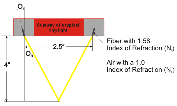
Sometimes, skew phenomena is also used as a design tool. The best example of this is the construction of a ring light. Because we can measure the amount of exit angle change using an adaptation of Snell’s Law, we can design ring lights with particular working distances, in a small package.
Consider the following:
A customer would like a 2.5″ ring light with working distance of 4″. To create this performance, we need to calculate the angle of the fiber in the ring to produce a shadow free spot of light 4″ from the ring.

Using some basic Geometry and Trig functions, we calculate the required exit angle of light to be 17.3°. Then we apply the following adaptation of Snell’s Law:

Getting a fiber angle (OI) of 10.84° (which we’ll round up to 11°)
Of course, this is just an example of how to apply the formula. To calculate the optimal fiber exit angle, we must also consider that light is emitted as a cone (not a straight line).
Ring lights and special applications aside, skew, or the absence of it, is a very good indicator of overall product quality and attention to detail. Fiber optic construction is a manual assembly process, so the experience of the assembly technician, and proper planning for manufacture make all the difference in the end result.
You can confirm the presence of skew by using a laser, outfitted with a beam expander, on the each end of the light guide. If either end projects circles on a reflective surface, consult with your supplier.

